Explore Component Relationships Through SOLIDWORKS Assembly Examples
Review independent educational examples covering assembly relationships, component access, movement considerations, and design alternatives.
Why SOLIDWORKS Assemblies
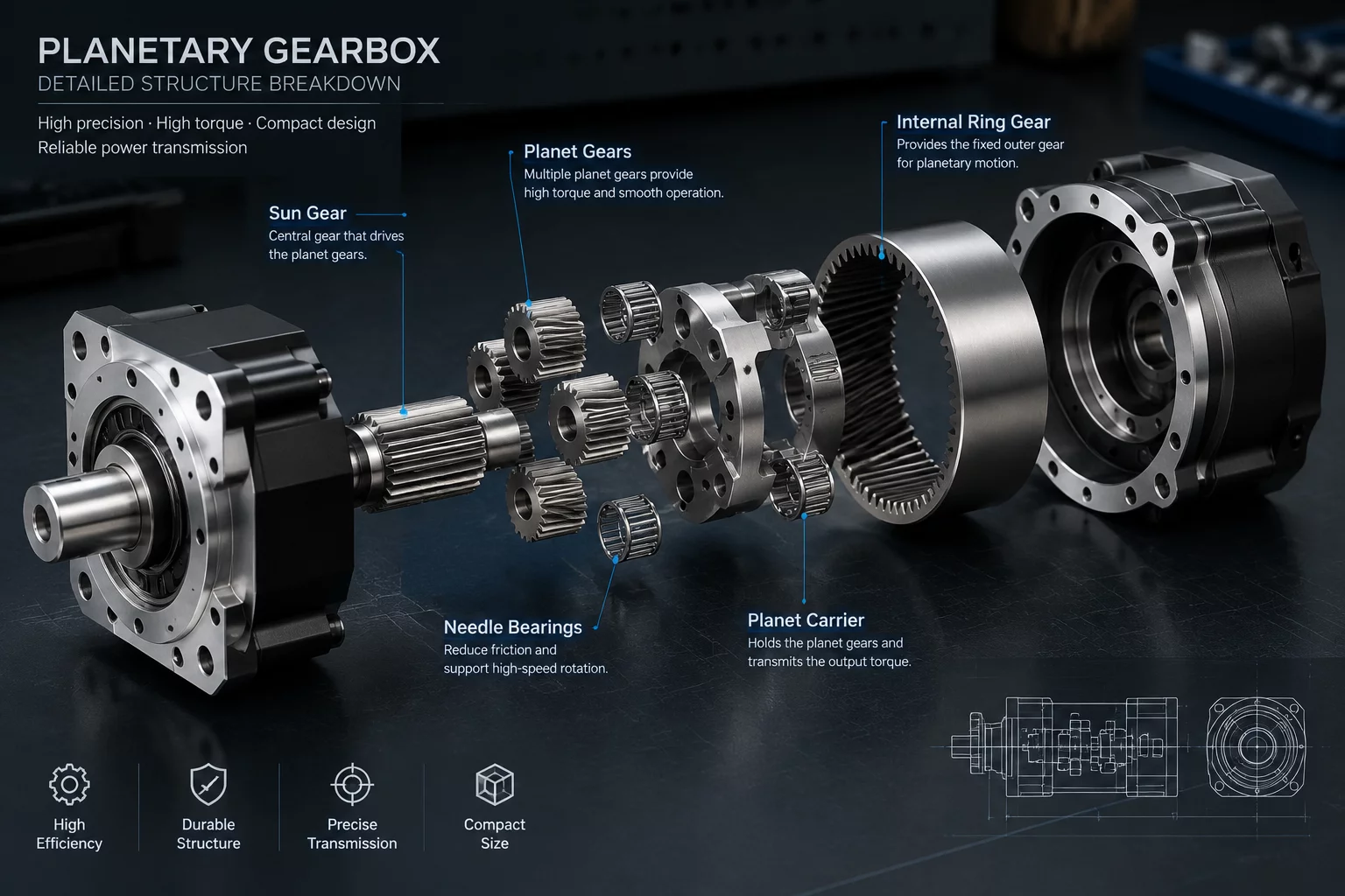
SOLIDWORKS includes tools for creating assemblies, as well as exploded views, which help illustrate the location and relationships of components. This makes it a suitable context for this atlas.
Inside an assembly model, components are positioned through mates — geometric relationships that define how parts align, face, or move relative to each other. Reviewing these mates makes it possible to trace dependencies between parts, check for interference, and see how a change to one component propagates through the whole structure.
Exploded views separate components along controlled paths while preserving their positional relationships, which is useful when studying assembly order and physical access to fasteners. Together with interference detection and clearance checks, they help reveal access and fitment problems before a design is finalized.
Subscribe to Receive Updated Guides on Component Interactions
Sign up to our newsletter to receive the latest news.