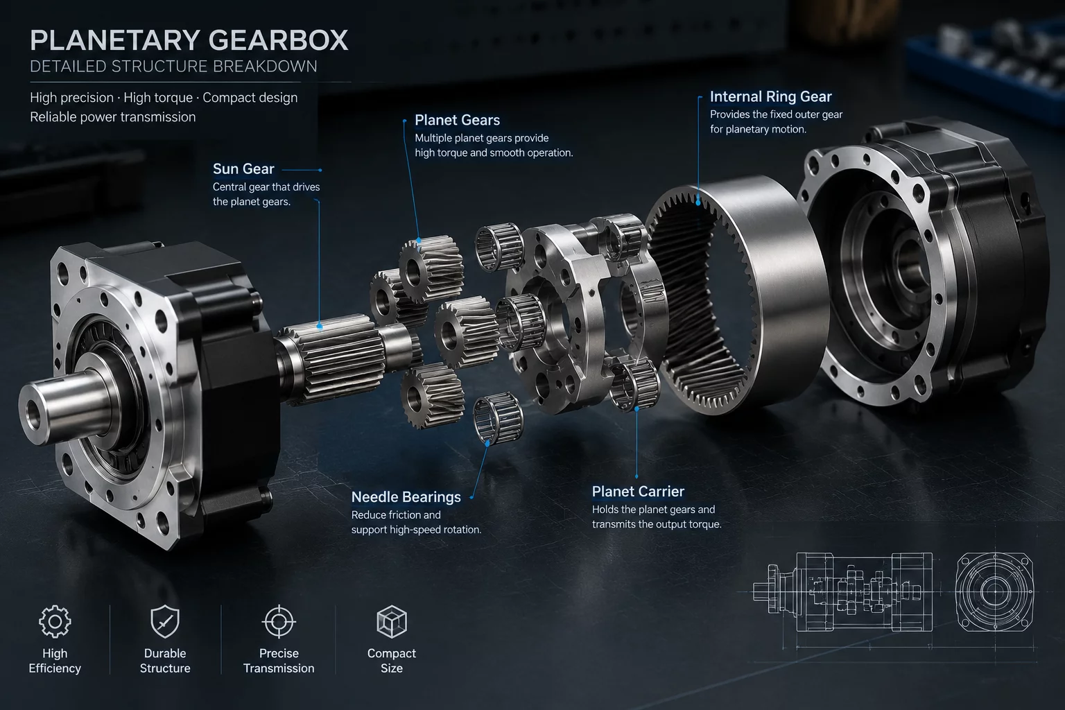
Planetary Gearbox Component Interface Map
Overview of Planetary Gearbox Mechanics
Planetary gearbox systems deliver exceptionally high power density and coaxial output capability within a compact footprint. Understanding how torque flows through the central sun gear, multiple planet gears, revolving carrier assemblies, and the stationary outer ring gear requires a detailed structural map. Each mating surface acts as a dynamic node where friction, contact stresses, thermal dissipation, and torsional deflections interact simultaneously. This interface map breaks down the physical boundaries between core transmission elements to assist mechanical engineers and students in predicting assembly performance under severe cyclic load profiles.
Primary Contact Nodes and Interface Behavior
The transmission architecture relies on balanced mechanical loading across distributed contact zones. Torque originates at the high-speed input shaft, moving directly into the external spur or helical teeth of the central sun gear. At this junction, sliding and rolling Hertzian contact stresses reach peak intensities.
Sun Gear to Planet Gear Mating Zone
Power transfers simultaneously across three or more planet gears. The engagement geometry demands strict pitch circle alignment to prevent eccentric tooth wearing. Equal force distribution depends on radial floating tolerances engineered into the sun shaft support bearings. As gear teeth mesh, lubrication film thickness dictates the transition between elastohydrodynamic lubrication and direct micro-asperity contact.
Planet Gear to Planet Carrier Journal Shafts
Each planet gear rotates around a stationary or needle roller bearing seated on carrier pins. The structural integrity of these pins dictates angular displacement during sudden load peaks. Higher torque shifts cause micro-bending along the pin length, altering the tooth contact pattern across the gear face width. Assembly maps must account for pin deformation to avoid premature surface spalling.
Planet Gear to Outer Ring Gear Mesh
The internal ring gear absorbs reaction torque and transfers structural forces directly into the outer gearbox housing. Because internal gear teeth present concave profile contact with convex planet teeth, contact stresses remain significantly lower than at the sun gear mesh. However, elastic deformation of the ring gear wall under radial forces can introduce high-frequency vibration if wall thickness is insufficient.
Interface Dynamics under Torsional Load
Operating conditions create intricate stress paths across the entire gear system. When external resistance changes, elastomeric seals, bearing retaining rings, and splined output shafts adapt to non-uniform strain patterns.
- Input Spline Engagement: Accommodates minor angular misalignment from the driving motor shaft while maintaining axial float.
- Carrier Support Bearings: Radial tapered roller bearings absorb combined axial thrust and radial bending moments generated by helical tooth angles.
- Casing Flange Interface: Bolted joint interfaces experience shearing strain, requiring calibrated fastener preload to maintain hermetic seal integrity.
- Oil Seals and Deflectors: Rotary lip seals isolate internal synthetic lubricants from external contaminants while experiencing localized thermal buildup at high shaft velocities.
Key Mechanical Specifications and Interface Tolerances
Achieving silent operation and long service life hinges on precise manufacturing tolerances across all mating components. The following breakdown highlights the fundamental mechanical metrics governed by this interface map.
- Backlash Range: 3 to 8 arcminutes depending on precision class and tooth mesh clearance settings.
- Carrier Pin Concentricity: Maintained within 0.005 mm relative to the primary rotational axis.
- Surface Finish (Ra): Tooth flanks ground to Ra 0.4 microns to maximize oil film continuity and minimize frictional heating.
- Hertzian Contact Limit: Engineered to withstand peak contact pressures up to 1,500 MPa during emergency stop cycles.
Diagnostic Insights and Interface Optimization
Analyzing component interface maps enables targeted diagnostic procedures when inspecting worn planetary gearboxes. Irregular wear patterns on planet pins often point directly to carrier misalignment or non-uniform bearing stiffness. By examining the load vector at each interface, engineers can optimize tooth profile modifications, adjust crown relief, and select suited thermal treatments to extend assembly lifetime.
Structured Reference Data for Mechanical Component Connections
Our contacts
Any questions? Contact us
Subscribe to Receive Updated Guides on Component Interactions
Sign up to our newsletter to receive the latest news.