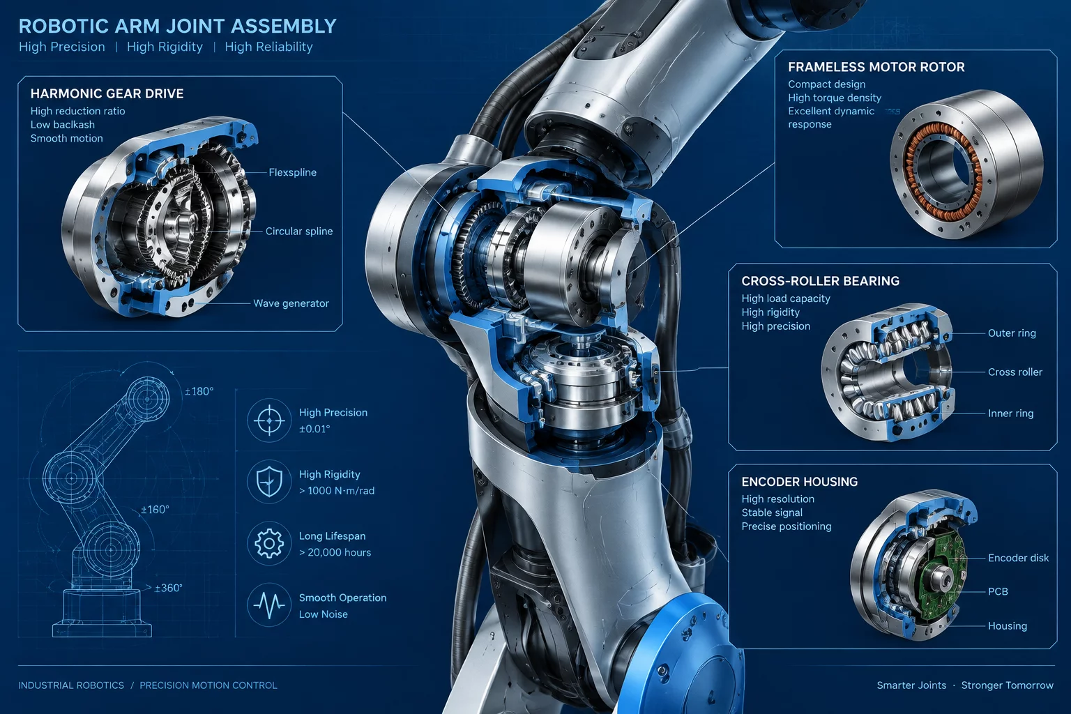
Robotic Articulated Arm Joint Interaction Map
Robotic Joint Architecture Principles
Modern articulated robot arms depend on extreme positioning repeatability and high dynamic response across multi-axis configurations. Each joint functions as a self-contained electro-mechanical module combining a high-torque frameless servo motor, precision harmonic drive gearhead, dual absolute encoders, cross-roller output bearings, and an integrated safety brake. Mapping the structural interfaces within a single robotic joint reveals how mechanical tolerances, thermal expansion, and dynamic loads affect overall end-effector precision.
Core Structural Subassemblies and Interface Nodes
Precision movement requires frictionless power transmission and zero torsional backlash. Forces pass through several distinct mechanical interfaces, each designed to balance rigid structural support with minimal mass inertia.
Frameless Motor Rotor to Harmonic Drive Wave Generator
The hollow rotor shaft connects directly to the elliptical wave generator hub using a friction lock radial clamping collar. High acceleration phases apply sudden shearing torque across this joint. Perfect concentricity prevents radial vibrations from transferring into the thin-walled flexible bearing ring surrounding the wave generator core.
Flexspline to Output Cross-Roller Bearing Hub
The deformable flexspline cup absorbs high rotational fatigue cycles while meshing with the rigid internal circular spline. Torque from the flexspline transfers into the output shaft assembly through a precision bolt circle pattern. Fastener torque specs are critical here; minor clamping variations distort the cylindrical flexspline geometry and trigger periodic transmission errors.
Cross-Roller Bearing to Joint Housing Interface
The primary cross-roller bearing supports combined axial, radial, and tilting moment loads experienced during rapid robotic arm maneuvers. The outer bearing ring bolts directly into the aluminum joint housing, while the inner ring fastens to the output flange. Radial preload settings in this bearing eliminate mechanical play, keeping arm deflection within sub-millimeter thresholds.
Thermal and Torsional Dynamic Considerations
Continuous robotic motion generates heat within motor windings and strain-wave contact surfaces. Differential thermal expansion can alter internal clearances across steel bearings and lightweight alloy housings.
- Thermal Expansion Compensation: Precision axial gaps allow motor shafts to expand without loading internal encoder discs.
- Encoder Disk Coupling: Micro-flexible bellows couplings isolate the optical disc from high-frequency shaft vibrations while preserving angular registration.
- Cable Feed-through Channel: Smooth internal polymer sleeves shield high-flex power and communication lines passing through the joint's hollow center from abrasion against rotating metallic walls.
- Electromechanical Brake Interface: Spring-applied brake pads press against a hardened steel disc mounted to the motor shaft during power-off holding states.
Interface Performance Parameters
Evaluating joint interface performance demands systematic measurement of dynamic compliance, backlash, and mechanical efficiency across operating temperatures.
- Positioning Repeatability: Maintained within +/- 0.01 mm at maximum arm reach under full rated payload.
- Torsional Stiffness: Engineered above 120 Nm/arcmin to resist structural drooping during rapid acceleration changes.
- Cross-Roller Bearing Preload: Calibrated to zero clearance with controlled axial stiffness preventing tilt under dynamic moments.
- Max Joint Speed: Capable of continuous angular velocities up to 180 degrees per second without thermal overload.
Practical Assembly and Maintenance Insights
Understanding joint interaction maps simplifies troubleshooting and overhaul routines in industrial automation settings. When joint position drift or abnormal noise occurs, engineers can trace force paths from the output hub back to the harmonic drive bearings. Proper alignment of cross-roller flanges and precise torque sequencing during reassembly ensure the robotic joint retains its factory accuracy over millions of continuous motion cycles.
Structured Reference Data for Mechanical Component Connections
Our contacts
Any questions? Contact us
Subscribe to Receive Updated Guides on Component Interactions
Sign up to our newsletter to receive the latest news.