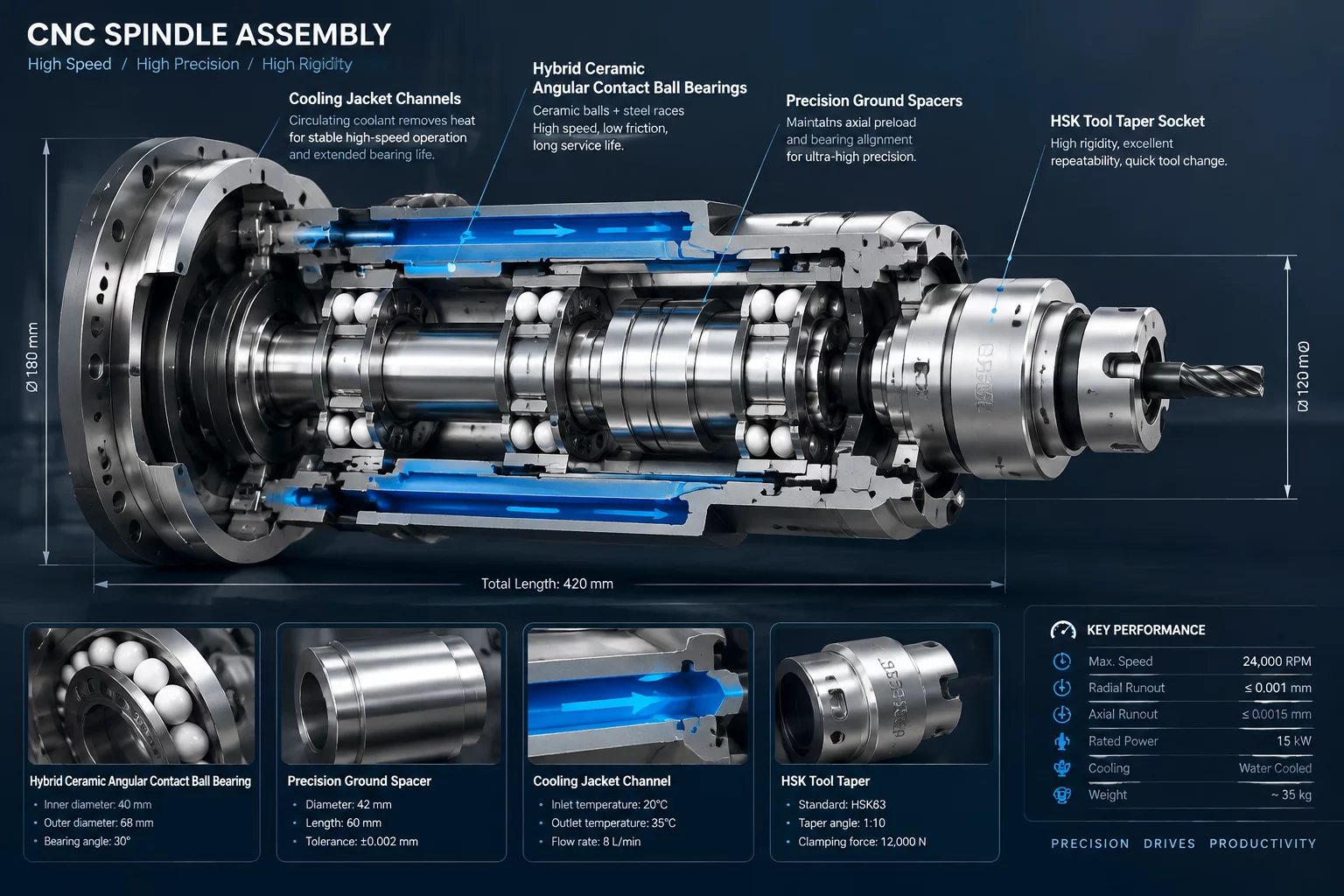
Multi-Axis CNC Spindle Bearing Assembly Interface Map
High-Precision CNC Spindle Systems
Multi-axis CNC machine spindles represent the pinnacle of high-speed rotational accuracy, stiffness, and thermal management. Operating at speeds exceeding 24,000 RPM while resisting intense cutting forces, the main spindle shaft relies on precision angular contact ceramic ball bearings arranged in tandem or quad sets. Mapping the interfaces within a CNC spindle reveals how hydraulic preloads, precision ground spacers, housing cooling jackets, and tool retention mechanisms maintain sub-micron rotational runout under heavy machining loads.
Critical Interface Nodes in Spindle Assemblies
Every interface within the spindle cartridge directly impacts cutting chatter, surface finish quality, and tool life during multi-axis machining operations.
Spindle Shaft to Angular Contact Bearing Inner Rings
Precision ground shaft journals seat the super-precision hybrid ceramic bearings. Micro-inch fits are essential; an overly tight interference fit expands the inner ring and destroys designated internal radial clearance, while a loose fit permits micro-fretting corrosion during high-speed rotation. Precision locknuts maintain axial positioning along ground shaft threads.
Bearing Outer Rings to Spindle Housing Sleeve
The housing sleeve contains precision ground bores holding outer bearing rings. Front bearing sets are axially fixed to absorb cutting thrust, while rear bearing sets float axially inside the housing against heavy-duty spring packs or hydraulic pistons. This floating arrangement accommodates thermal growth of the steel spindle shaft during prolonged machining runs.
Tool Holder Taper to Spindle Nose Socket
The steep HSK or CAT taper interface relies on simultaneous contact across both the conical taper and the flat spindle nose face. Internal drawbar spring packs pull the tool holder retention knob with high force, seating face-to-face contact tightly to eliminate radial tool runout under side-milling forces.
Thermal Expansion and Dynamic Balance Controls
High rotational speeds create frictional heat in bearing raceways and motor stators, requiring targeted thermal isolation techniques.
- Cooling Jacket Interface: Spiral fluid channels encircling the spindle outer housing remove heat generated by integrated motor windings.
- Air Purge Sealing Gland: Positive air pressure seals behind labyrinth rings prevent cutting coolant mist and fine chips from entering clean bearing cavities.
- Ground Bearing Spacers: Matched length inner and outer spacers set precise axial preload across angular contact bearing sets.
- Drawbar Gripper Collet: Four-segment hardened steel jaws clamp the tool holder pull stud securely within the rotating shaft bore.
Interface Performance and Mechanical Specs
Maintaining high-precision machining tolerances relies on strict limits across all rotational interfaces.
- Spindle Nose Radial Runout: Kept below 0.001 mm (1 micron) measured at maximum rotational velocity.
- Bearing Operating Temperature: Controlled within +/- 2°C using active liquid chiller circuits.
- Drawbar Clamping Force: Ranges from 15 kN to 45 kN depending on spindle frame size.
- Dynamic Balance Grade: Balanced to ISO 1940 G 0.4 standard to suppress high-frequency vibration during finishing cuts.
Diagnostic Applications of the Spindle Interface Map
Mapping spindle component interfaces streamlines rebuilt routines and predictive maintenance programs. Unexpected thermal spikes across front bearing seats often indicate lubricant breakdown or excessive axial preload caused by thermal growth failure. Inspecting tool holder contact faces under blue dye transfer tests reveals taper wear early, preserving spindle accuracy and avoiding costly machine downtime.
Structured Reference Data for Mechanical Component Connections
Our contacts
Any questions? Contact us
Subscribe to Receive Updated Guides on Component Interactions
Sign up to our newsletter to receive the latest news.