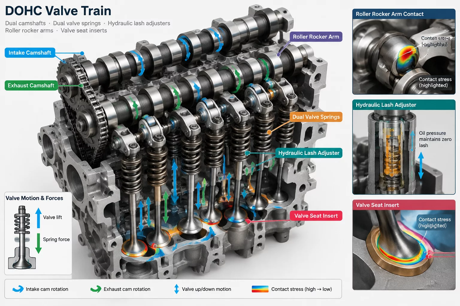
Internal Combustion Engine Valve Train Interaction Map
Valvetrain Dynamics and Component Coupling
The valve train controls the precise timing and volumetric efficiency of internal combustion engines by opening and closing intake and exhaust valves in sync with the crankshaft. Modern overhead camshaft (DOHC) valve trains operate under extreme dynamic loads, high acceleration rates, and thermal stresses. Mapping component interactions—from camshaft lobes down to valve seats—provides insight into friction reduction, valvetrain stability, and valve timing accuracy across varying engine speeds.
Primary Contact Nodes in Valvetrain Assemblies
Every movement in the valve train relies on direct sliding or rolling contact interfaces that must endure millions of loading cycles without loss of dimensional tolerance.
Camshaft Lobe to Roller Rocker Arm / Hydraulic Tappet
As the camshaft turns, the cam lobe profile pushes against a rolling needle-bearing follower or flat-face bucket tappet. The contact zone shifts continuously along the lobe surface. Lubrication holes deliver engine oil directly to this high-pressure sliding interface, preventing galling and reducing friction losses.
Hydraulic Lash Adjuster (HLA) to Rocker Arm Pivot
Hydraulic lash adjusters maintain zero mechanical clearance between the cam lobe and valve stem tip across all operating temperatures. Engine oil enters the internal HLA plunge chamber through a tiny ball check valve. Under load, oil trapped in the chamber acts as a rigid hydraulic column, transferring motion while automatically taking up thermal expansion gaps.
Valve Stem Guide to Cylinder Head Bore
The ground steel or bronze valve guide controls linear motion of the valve stem, keeping the valve head centered on its seat ring. Precision diametral clearances prevent valve stem tipping while allowing a controlled oil film to lubricate the sliding interface. Elastomeric valve stem seals at the top of the guide prevent excess oil from leaking down into the intake and exhaust ports.
Force Path and High-Speed Dynamics
Valvetrain stability depends on balancing spring forces against dynamic component inertia at high engine RPM.
- Valve Spring Retainer Locks (Keepers): Tapered two-piece split keepers wedge into grooves on the valve stem tip, clamping the retainer under spring force.
- Dual Concentric Valve Springs: Inner and outer springs with opposing helix angles prevent valve float and dynamic surge resonance at high engine speeds.
- Valve Face to Seat Ring Interface: Hardened stellite seat inserts absorb high thermal energy while establishing a gas-tight seal against combustion chamber pressures.
- Variable Cam Phaser Splines: Helical internal splines adjust camshaft phase angle relative to the drive sprocket, shifting valve timing dynamically.
Critical Valvetrain Technical Metrics
Achieving stable high-RPM valvetrain performance demands exact geometric tolerances and rigid material selection.
- Max Valve Lift: Typically ranges from 8.5 mm to 14.0 mm based on engine tuning profile.
- Valve Stem Clearance: Maintained between 0.020 mm and 0.045 mm to ensure smooth guiding without tilt.
- Valve Spring Preload: Calibrated between 300 N (closed) and 850 N (fully open) to prevent valve floating.
- Contact Surface Hardness: Cam lobe flanks nitrided or induction hardened to exceed 60 HRC.
Diagnostic Value of Valvetrain Mapping
Mapping valve train interfaces gives engine builders clear diagnostic pathways when analyzing valvetrain noise or loss of cylinder compression. Wear marks on rocker arm pads point toward hydraulic lash adjuster failure or contaminated engine oil. By reviewing interface force vectors, engineers can refine cam lobe profiles and spring rates to reduce friction and extend component life.
Structured Reference Data for Mechanical Component Connections
Our contacts
Any questions? Contact us
Subscribe to Receive Updated Guides on Component Interactions
Sign up to our newsletter to receive the latest news.