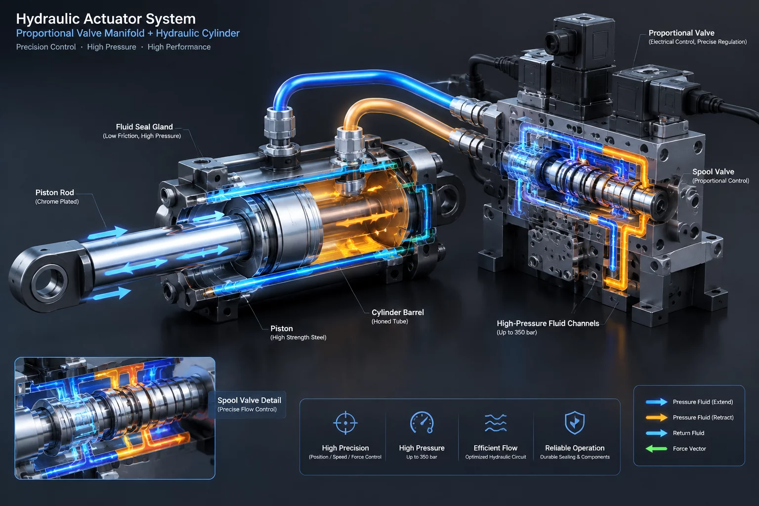
Hydraulic Actuator & Valve Interface Scheme Map
Fundamentals of Fluid-Mechanical Actuation Systems
Hydraulic actuation systems convert fluid energy into linear or rotary motion through tight dynamic seals, precisely machined valve spools, and heavy-duty structural cylinders. The interaction between fluid pressure zones and mechanical components creates complex loading environments. Interface mapping provides a complete view of structural contact surfaces, pressure boundaries, seal glands, and mechanical linkages across hydraulic systems, enabling efficient design and failure analysis.
Mechanical-Fluid Interface Zones
A hydraulic circuit operates effectively when hydraulic oil stays contained while transferring immense forces through moveable mechanical interfaces.
Proportional Valve Spool and Sleeve Interface
The control valve spool moves inside a hardened steel sleeve with diametral clearances under 5 microns. Fluid metering relies on precise notch geometry cut into the spool lands. Radial hydraulic forces must balance across opposing lands to avoid spool binding against the sleeve wall, a phenomenon known as hydraulic lock.
Piston Rod Seal and Wiper Assembly
The cylinder head gland houses primary U-cup rod seals, secondary buffer seals, and outer dust wipers. As the chrome-plated piston rod extends and retracts, fluid film lubrication coats the rod surface without leaking past the elastomeric seals. Microscopic surface finish parameters on the rod dictate seal friction and wear rates over millions of stroke cycles.
Piston Wear Rings and Cylinder Bore Contact
The piston assembly separates the extension and retraction pressure chambers inside the cylinder barrel. Composite guide rings absorb side loads caused by structural bending moments, preventing direct metal-to-metal contact between the steel piston and honed cylinder barrel wall. Piston seals maintain fluid separation under differential pressures exceeding 350 bar.
Force Transmission and Seal Integrity
System reliability depends on how mechanical components accommodate severe pressure spikes and external structural flexure.
- Cylinder End-Cap Threaded Interfaces: High tensile thread engagement maintains axial clamping forces resisting continuous internal static and dynamic fluid pressures.
- Clevis Pin and Spherical Bearing Joints: Mounts absorb non-axial loading angles, preserving pure linear movement along the cylinder centerline.
- Valve Manifold Surface Flanges: O-ring seals seated in precision grooves maintain fluid-tight sealing across high-pressure subplate mounting surfaces under dynamic pressure pulses.
- Damping Cushion Plungers: Tapered sleeves enter end-cap chambers near stroke limits, restricting fluid egress to generate hydraulic braking forces.
Critical Technical Metrics
System stability depends on rigid tolerances and material compatibility across all dynamic fluid boundaries.
- Operating Pressure Class: Designed for continuous system pressures up to 35 MPa (350 bar).
- Spool Clearance Range: Maintained between 0.002 mm and 0.006 mm for minimal internal leakage.
- Rod Surface Roughness (Ra): Honed and hard-chrome plated to Ra 0.1 - 0.2 microns to maximize seal life.
- Fluid Viscosity Range: Compatible with ISO VG 32 to VG 68 mineral and synthetic hydraulic fluids across -20°C to +80°C operating spans.
Diagnostic Utility of Interface Mapping
Detailed interface schemes allow technicians and system designers to isolate degradation sources quickly. Excessive internal bypass flow can be traced directly to wear patterns on piston guide rings or erosion along valve spool metering edges. By understanding structural load distribution across gland seals and mounting linkages, maintenance schedules can be planned around predictable component lifespans.
Structured Reference Data for Mechanical Component Connections
Our contacts
Any questions? Contact us
Subscribe to Receive Updated Guides on Component Interactions
Sign up to our newsletter to receive the latest news.